Research Article Archive Versions 1 Vol 3 (1) : 20030104 2020
Download
A Study of 2D Assist Feature Placement
: 2019 - 10 - 11
: 2020 - 03 - 30
2341 17 0
Abstract & Keywords
Abstract: Sub-resolution assist features have been widely recognized in lithography patterning. In general, the insertion of assist features in optically adjacent space around main designed features, will change the aerial image intensity profiles of corresponding main features. Optimizing assist feature placement lets the main feature obtain optimal or better image contrast, better imaging resolution and depth of focus (DOF). Recent EUV lithography development, however, imposes strict budget of edge placement error and process window control causing assist features to become more and more complex. In this domain, 1D assisting feature can no longer meet such tight requirements, and 2D assisting features have become necessary in the semiconductor industry. In this paper, the process window and edge placement error evaluations of different 2D assist feature types are reviewed, along with their associated run time and memory consumption. Various types of 2D assist features are evaluated, including 45-degree disconnected assist features, 45-degree connected assisting features, Manhattan only assist feature arrays, and so on. To generate the assist features, the model-based assisting feature rule table is first generated using the optical model as the reference. The rule table is then split into different rule sets by considering the dimensions and types of assisting features. Finally, the CD variations across process window are evaluated as the success criteria of each assist feature rule sets. In addition, an inverse lithography technology (ILT) based approach is proposed to generate the optimized rule table, as ILT is well known to have considerable benefits in finding the best pattern solutions to improve process window, 2D CD control, and resolution in the low K1 lithography regime. At the end of this paper, the summary discusses how the assisting feature placement can be further optimized using leading-edge technologies like machine learning.
Keywords: Assist Feature; Inverse Lithography Technology; Low K1 Lithography; Machine Learning
1.   Introduction
As the down scaling of fabrication rules continues, the industry is now facing the challenge of extending the life of optical lithography when the printed size is close to the resolution limit of the exposure tool. With the introduction of EUV lithography technology, Moore’s law remains effective but exposes even more strict CD control and process window requirements of the patterning process. Assist features are well known for their ability to reduce the non-uniformity of the main feature design pitches across the entire layout. Generally, there are two approaches to accomplish the assist feature placement: (i) rule-based methodology, and (ii) model-based methodology.
For the rule-based approach, the result is accurate, but the derivation of the assist feature rules requires excessive wafer measurements, and test masks with the complex rule tables. As a result, research in recent years has mainly focused on the model-based assist feature methodology or inverse lithography technology (ILT). Still, rule-based assist features are widely used because they require less mask synthesis run time and they provides better consistency across the chips. For the non-leading-edge technology nodes (e.g. 130nm down to 65nm) in which assist features are required, the rule-based assist features are enough.
To speed-up the creation of the rule tables for the assist feature placement, a model-assisted rule tables (MART) approach is proposed. The mask-making and wafer-printing process needed to collect metrics for creating the rule table are replaced by lithographic simulations.
2.   Model-assisted Rule Tables
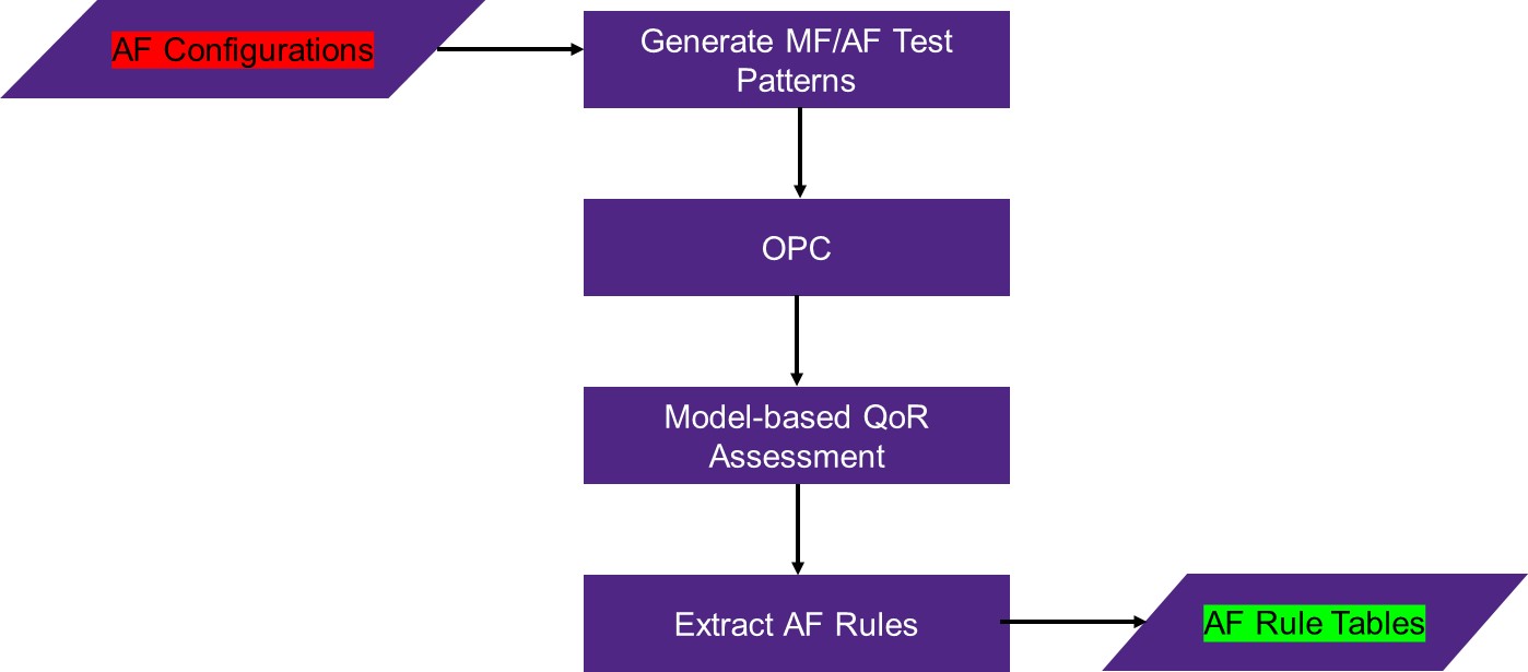
As discussed in the previous section, the rule-based assist features are well received due to their mask synthesis performance and consistency. There have been studies years before to propose the hybrid assist feature implementation methodology by using process window models to select assist feature rules [1]. There are still rooms to improve by automating such evaluating processes. To speed-up the rule table generation process, the model-assisted rule tables are offered in this paper. Figure 1 shows the general flow of MART. After the main feature test patterns are generated, there are different configurations to insert the assist features. OPC is then applied on these test patterns with assist features. Next, a process window model is used to evaluate the quality of different assist feature configurations. Finally, based on the results, the best assist feature configurations will be produced.
Compared with the traditional rule table exaction process, the key point here is that the mask-making, wafer-printing and data measurements are all replaced by lithographic simulations. This approach significantly improves the turn-around-time and efficiency evaluating assist feature configurations and rules.


Figure 1.   Data flow for MART - inputs are shown in red, outputs are shown in green (MF: main feature, AF: assist feature).
For 1D assist features, the rule table is relatively simple. The user only needs to specify the assist feature width and the distance between main feature and assist feature or between assist feature and assist feature.
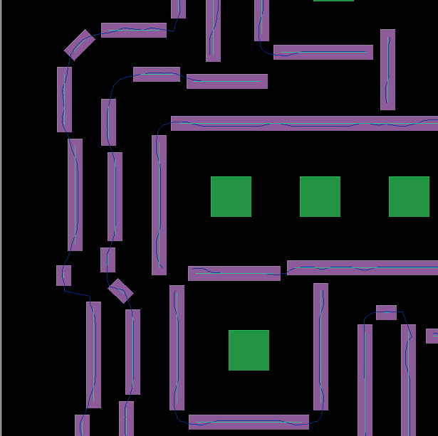
For 2D assist features, the rule table is much more complicated. A third dimensional parameter is introduced which defines the angle of the assist feature relative to the main feature. Figure 2 shows a typical layout with 2D assist feature placement. The definition of such rule is much more complicated than the 1D assist feature rule table. Under the 2D scenario, the model-assisted approach shows even bigger advantages by automating the process to select the best 2D assist feature rule tables.


Figure 2.   A typical layout with 2D assist feature placment
3. Process Window Evaluation of Different 2D Assist Feature Types
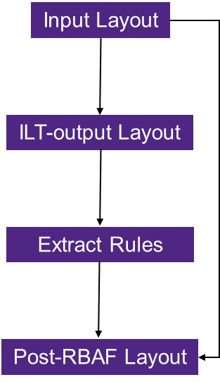
There are many choices influencing the final 2D assist feature placement on the Manhattan skeleton. For example, the assist features may be connected or disconnected, they may be Manhattan only, and Manhattan only assist features may enforced mask rule checks (MRC).
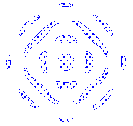
To evaluate the impact of the different assist feature options, we run the post-OPC lithography rule checks, and measure the process variation band as the success criteria of the assist feature placement. The experiment is based on a 193nm immersion lithography process for a contact layer with the target CD of 90nm. Figure 3 shows the different 2D assist feature placement options that were tested, from the manual 2D placement to the MART2D with enforced MRC.
Table 1 provides the process variations that were extracted for each of the different placement options. The minimum and maximum CD metrics are the respective lower and upper CD values across the process windows, reported as a percentage of target CD. A smaller absolute value means a better CD control through process window.
From the test data, it is found that the process window improvement is not sensitive to the assist feature shapes. Some arbitrary changes in the assist feature shapes may even degrade the process window metrics. What is more important is the assist feature placement rules themselves. MART2D offers a good way to find such rules. The data shows that the best solution is obtained from MART2D with enforced MRC to filter out some unwanted small shapes. Such a methodology provides the smallest CD variation range through the process window.

(a)


(b)


(c)


(d)


(e)


(f)

Figure 3.   Different 2D assist feature placement candidates: (a) Manual 2D assist feature placment, 45 degree only, (b) All angle disconnected 2D assist feature placement, (c) All angle connected 2D assist feature placement, (d) Manhattan only 2D assist feature placment, (e) MART2D assist feature placement, without MRC, and (f) MART2D assist feature placment, MRC enforced.
Table 1.   Comparisons with different 2D assist feature placement methodology
ScenariosMinimum CD (%)Maximum CD (%)Range (%)
a) Manual, 45 degree only-15.5817.6833.26
b) Manual, All-angle disconnected-18.3818.7637.14
c) Manual, All-angle connected-17.7619.2036.96
d) Manual, Manhattan only-17.9919.2137.21
e) MART2D-13.9916.9130.90
f) MART2D+MRC-13.9816.8930.87
4.   ILT-based Assist Feature Generation Flow
ILT is well known as a rigorous approach to determine the ideal mask shapes that will produce the desired on-wafer results. The key distinctive feature of ILT is its ability to broadly explore wide solution space. The mask features that do not print on the wafer naturally transform to assist features.
ILT-based assist feature generation flow is also introduced in this paper. Figure 4 takes an isolated contact as an example. MART uses model-based ILT to establish the ideal AF placements for optimal process window. Then using this as a reference 2D rules are automatically extracted to enable fast rule-based AF placement with comparable coverage and quality of results as ILT. These rules can then be used directly to place 2D ILT-like AFs very quickly.


Figure 4.   ILT-based assist feature generation flow.
5.   Summary and Discussions
In this paper, the model-based 2D assist feature rule table is introduced. In addition, a process window evaluation of different 2D assist feature placement options is presented. From the percentage of CD variations across process window, it was found that MART2D with enforced MRC clean-up can achieve the best through process window behaviors. Finally, the ILT-based assist feature generation flow is proposed.
Further studies can be performed on this newly proposed methodology, to evaluate its potential benefit over the traditional MART2D. In the future, we may also expect the methodology to become accurate and reliable, by collecting data over many studies and incorporating artificial intelligence and machine learning techniques.
Acknowledgments
The authors of this paper would like to thank Daniel Xu, Yongdong Wang, Guangming Xiao and Travis Brist for their helpful discussions and supports.
[1] L. Zhu, X. H. Kang, Y. L. Gu, et al, “Hybrid Sub-Resolution Assisting Feature Implementation Methodology by Process Window Aware Optical Proximity Correction Model”, Japanese journal of applied physics 48(3), 036502 (2009).
[2] X. J. Su, P. Z. Gao, Y. Y. Wei, et al, “SRAF rule extraction and insertion based on inverse lithography technology”, Proc. of SPIE Vol. 10961, 109610P (2019).
[3] K. Hooker, B. Kuechler, A. Kazarian, et al, “ILT optimization of EUV masks for sub-7nm lithography”, Proc. of SPIE Vol. 10446, 1044604 (2017).
[4] L. Y. Pang, Y. Liu, D. Abrams, et al, “Inverse lithography technology (ILT): a natural solution for model-based SRAF at 45-nm and 32-nm”, Proc. of SPIE Vol. 6607, 660739 (2007).
[5] M. Guajardo, Y. L. Chen, P. Brooker, et al, “Investigation of machine learning for dual OPC and assist feature printing optimization”, Proc. of SPIE Vol. 10962, 109620E (2019).
[6] K. Hooker, A. Kazarian, X. B. Zhou, et al, “New methodologies for lower-K1 EUV OPC and RET optimization”, Proc. of SPIE Vol. 10143, 101431C (2017).
[7] A. Lutich, “Alternative to ILT method for high-quality full-chip SRAF insertion”, Proc. of SPIE Vol. 9426, 94260U (2015).
[8] K. Lucas, C. Cork, J. Cobb, et al, “Patterning control budgets for the 32-nm generation incorporating lithography, design and RET variations”, Proc. of SPIE Vol. 6520, 65200N (2007).
[9] L. Y. Pang, Y. Liu, D. Abrams, “Inverse lithography technology (ILT): What is the impact to the photomask industry?”, Proc. of SPIE Vol. 6283, 62830X (2006).
[10] F. L. Chin, T. P. Lukanc, “Understanding and application of constructive, destructive SRAF”, Proc. of SPIE Vol. 6924, 69242V (2008).
[11] L. Y. Pang, G. Dai, T. Cecil, et al, “Validation of inverse lithography technology (ILT) and its adaptive SRAF at advanced technology nodes”, Proc. of SPIE Vol. 6924, 69240T (2008).
[12] R. Viswanathan, J. T. Azpiroz, P. Selvam, “Process optimization through model base SRAF printing prediction”, Proc. of SPIE Vol. 8326, 83261A (2012).
[13] A. Omran, G. Lippincott, J. Schacht, et al, “Can fast rule-based assist feature generation in random-logic contact layout provide sufficient process window?”, Proc. of SPIE Vol. 8326, 83261P (2012).
[14] S. Jayaram, P. Lacour, J. Word, et al, “Model-based SRAF solutions for advanced technology nodes”, Proc. of SPIE Vol. 8886, 88860P (2013).
[15] M. C. Tsai, S. Nojima, M. Miyairi, et al, “A full chip MB-SRAF placement using the SRAF guidance map”, Proc. of SPIE Vol. 7823, 78233Q (2010).
Article and author information
Liang Zhu
Liang.Zhu1@synopsys.com
Barry Ma
Lin Shen
Kevin Beaudette
Publication records
Published: March 30, 2020 (Versions1
References
Journal of Microelectronic Manufacturing