Research Article Archive Versions 3 Vol 1 (2) : 18010202 2018
Download
Compressive Sensing Approaches for Lithographic Source and Mask Joint Optimization
: 2018 - 11 - 26
: 2018 - 12 - 13
2620 41 0
Abstract & Keywords
Abstract: Source and mask joint optimization (SMO) is a widely used computational lithography method for state-of-the-art optical lithography process to improve the yield of semiconductor wafers. Nowadays, computational efficiency has become one of the most challenging issues for the development of pixelated SMO techniques. Recently, compressive sensing (CS) theory has be explored in the area of computational inverse problems. This paper proposes a CS approach to improve the computational efficiency of pixel-based SMO algorithms. To our best knowledge, this paper is the first to develop fast SMO algorithms based on the CS framework. The SMO workflow can be separated into two stages, i.e., source optimization (SO) and mask optimization (MO). The SO and MO are formulated as the linear CS and nonlinear CS reconstruction problems, respectively. Based on the sparsity representation of the source and mask patterns on the pre-defined bases, the SO and MO procedures are implemented by sparse image reconstruction algorithms. A set of simulations are presented to verify the proposed CS-SMO methods. The proposed CS-SMO algorithms are shown to outperform the traditional gradient-based SMO algorithm in terms of both computational efficiency and lithography imaging performance.
Keywords: Computational lithography; source mask optimization (SMO); compressive sensing (CS); inverse problem
1.   Introduction
Most of the large-scale integrated circuits (IC) are today fabricated by optical lithography processes[1] . The left side of Figure 1 shows a simplified sketch of the deep ultraviolet (DUV) immersion lithography system that transfers the layouts of ICs from the lithography mask onto the wafer. An ArF light source with 193nm wavelength is used to illuminate the lithographic mask, where only a portion of the light rays transmits through the mask openings according to the layout pattern carved on the mask. Then, the projection optics collects a set of diffraction orders from the mask to form the partially coherent image on the wafer, which is also referred to as the aerial image. Considering the photoresist effect, the binary print image on the wafer can be approximated as the hard threshold version of the aerial image. Due to the continuous shrinkage of the critical dimensions (CD) of IC layouts, image resolution and fidelity become important performance metrics for the development of the advanced optical lithography tools and processes.


Figure 1.   The sketch of DUV optical lithography system and SMO approach.
The semiconductor industry has heavily relied on computational lithography techniques to push the limits of lithographic resolution and image fidelity[2,3]. Source and mask joint optimization (SMO) is a widely used computational lithography technique to improve the yield of semiconductor manufacturing. Compared to individual source optimization (SO) and individual mask optimization (MO), SMO techniques jointly optimize the illumination configurations of the lithography tools and the geometric patterns carved on the mask, thus bring in higher degrees of optimization freedom. In the past, a number of SMO algorithms have been proposed in literature[4,5]. In order to generate the freeform source and mask patterns, pixelated SMO methods have been introduced, where both of the source and mask patterns to be optimized are gridded into arrays of pixels[611]. Gradient-based algorithms are effective to solve for the inverse pixelated SMO problems. However, traditional gradient-based algorithms are not efficient enough to achieve optimality in pixelated SMO results for complex layout patterns, especially under the vector lithography imaging model[9]. Thus, computational efficiency has become a big challenge in the development of pixelated SMO techniques.
Recently, compressive sensing (CS) theory has be explored to efficiently solve for numerous inverse problems[1214]. In particular, a set of linear CS and nonlinear CS approaches have been successfully developed respectively for the SO and MO problems in the optical lithography realm[1517]. Inspired by these previous works, this paper proposes to use the CS approaches to efficiently solve for the pixelated SMO problem. To our best knowledge, this paper is the first to develop the fast SMO algorithms based on the CS framework, which is referred to CS-SMO hereafter. The proposed CS-SMO method consists of two basic stages, i.e., the SO stage and the MO stage. According to the imaging model of the lithography systems, the SO and MO sub-problems can be formulated under linear CS and nonlinear CS frameworks, respectively. The layout pattern is then downsampled to reduce the dimensionality of the cost function in optimization procedure, thus the computational complexity of the CS-SMO algorithms is reduced accordingly. Based on the sparsity assumption of the source and mask patterns, the underdetermined SMO problem can be efficiently solved by the sparse image reconstruction algorithms. This paper presents a set of simulations to verify and assess the proposed CS-SMO method and compares it to the traditional gradient-based SMO algorithm. The superiority of the CS-SMO method will be proved in terms of both computational efficiency and lithography imaging performance. In the following, Section 2 establishes the optimization model for the CS-SMO problem. Section 3 develops the fast SMO algorithm based on the CS framework. Section 4 presents the simulations and comparison. The paper will be concluded in Section 5.
2.   Optimization Model of CS-SMO Problem
According to the Abbe’s imaging model for optical lithography systems, the aerial image projected on the wafer can be calculated as[9]:
, (1)
where denotes the source pattern, is the normalization factor, and denotes the mask pattern. The matrix represents the oblique incidence effect of the light rays. is the point spread function of the lithography system. The notations and ⊙ represent the convolution and the entry-wise multiplication operators, respectively. Using a hard threshold function to depict the photoresist effect, the print image after photoresist development can be calculated as
, (2)
where is the hard threshold function, and is the process threshold value.
2.1.   SO Model based on the Linear CS Framework
For the SO stage in the CS-SMO process, Equation (1) can be converted into the following system of linear equations:
, (3)
where and are the raster-scanned vectors of the source pattern and the aerial image , respectively. is referred to as the illumination cross coefficient (ICC) matrix that represents the relationship between the aerial image and the source pattern[15, 16]. Suppose that can be sparsely represented on the basis , i.e., , where is a K-sparse coefficient vector, where only K (K ⊙ N) elements in are significant.
Based on the linear CS approaches proposed in Reference [15] and Reference [16], the SO problem can be modelled as the following l1 -norm image reconstruction problem:
, (4)
where and respectively represent the l1 -norm and l2 -norm of the arguments, and is the bounded error term. In order to reduce the dimensionality of the SO problem, we sparsely sample the layout pattern according to the blue noise distribution, and thus select monitoring pixels on the layout. In Equation (4), and represent the ICC matrix and the raster-scanned vector of target layout corresponding to the monitoring pixels, respectively. is a random or adaptive projection matrix used to further reduce the dimension of the system of linear equation[15, 16].
2.1.   MO Model based on a Nonlinear CS Framework
Given the two-dimensional target layout pattern , the cost function of the MO stage in CS-SMO problem can be established as [17]
, (5)
where is a weight matrix used to emphasize or deemphasized the image errors in different layout regions. The dimensionality of the cost function can be reduced by the equal interval downsampling method on the layout proposed in Reference [17]. Given the downsampling rate , the downsampled versions of weight matrix, target pattern and print image are respectively denoted by . In addition, the defocus effect and exposure variation should be incorporated in the cost function to improve the robustness of the lithography process. In this way, the cost function in Equation (5) can be modified as:
, (6)
where the single prime and double prime respectively indicate the variables on the focal plane and the defocus plane. The parameter represents the exposure variation of the light source. Based on the cost function in Equation (6), the MO problem can be modelled as a nonlinear CS reconstruction problem:
. (7)
3.   SMO Algorithm based on CS Framework
Based on the optimization models mentioned above, this section describes the CS algorithms used to solve for the SMO problem. The flowchart of the proposed CS-SMO algorithm is summarized in Table 1. The proposed CS-SMO algorithm is implemented in a sequential model. We first iteratively optimize the source pattern by fixing the mask pattern, and then iteratively optimize the mask pattern given the source fixed. After the MO stage, the CS-SMO algorithm is terminated. In this paper, the linear Bregman (LB) algorithm[18, 19] and the gradient projection for sparse reconstruction (GPSR) algorithm[20] are used to solve for the SO problem in Equation (4). On the other hand, we use the iterative hard thresholding (IHT) method[21] to obtain the optimal mask pattern from Equation (7).
Table 1.   The flowchart of the proposed CS-SMO algorithm.
Step1Initialize the source, mask and other parameters
Step2Update the source variables using the GPSR or LB algorithms until the termination condition is satisfied
Step3Updates the mask variables using the IHT algorithm until the termination condition is satisfied
Step4Output the optimized source and mask patterns
4.   Simulations
This section provides simulation results of the proposed CS-SMO method, and compares it to the traditional gradient-based SMO algorithm. In the following simulations, we use an immersion lithography system with 1.2 numerical aperture and a four-fold demagnification factor for the projection optics.
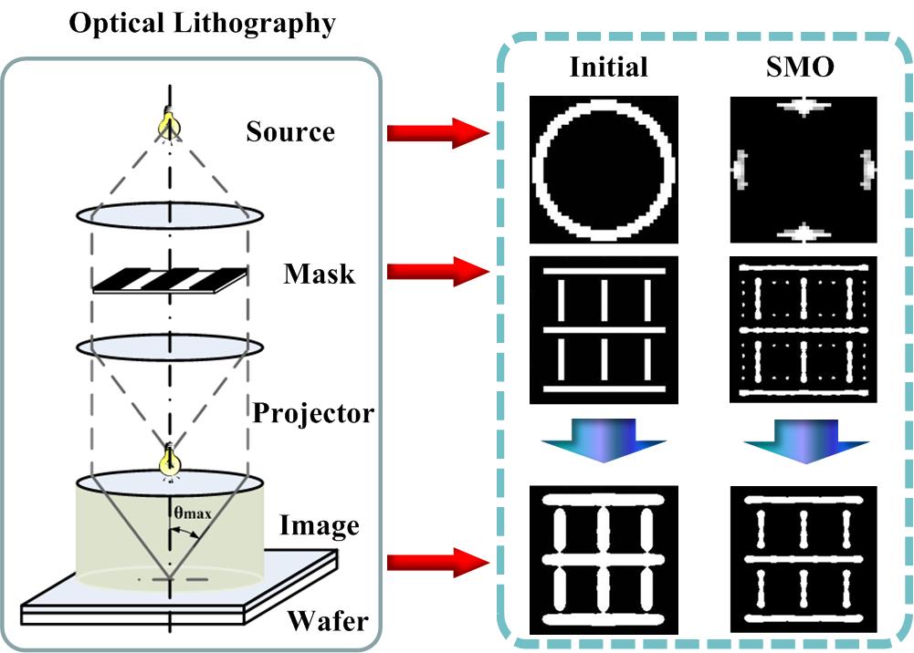
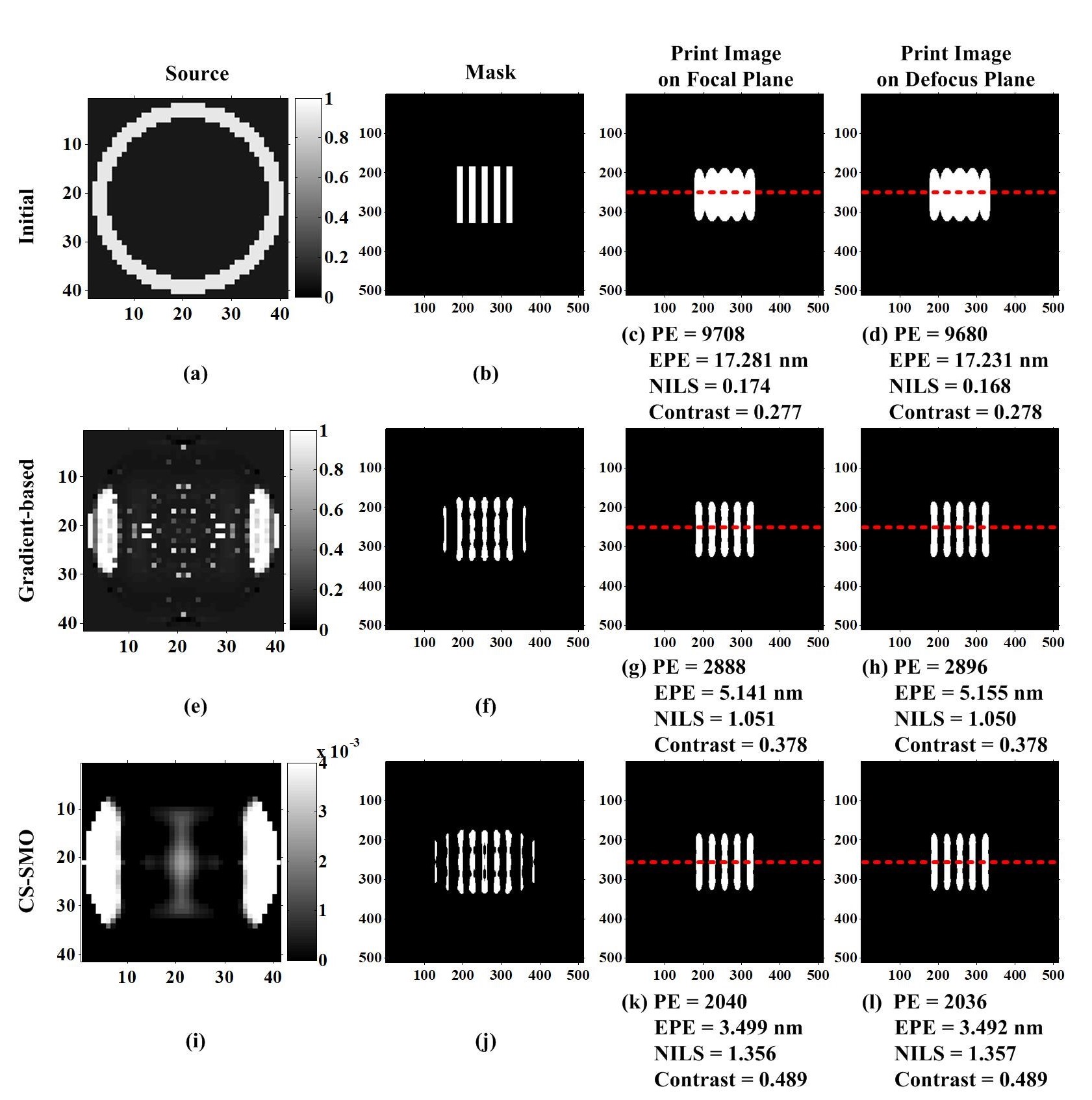
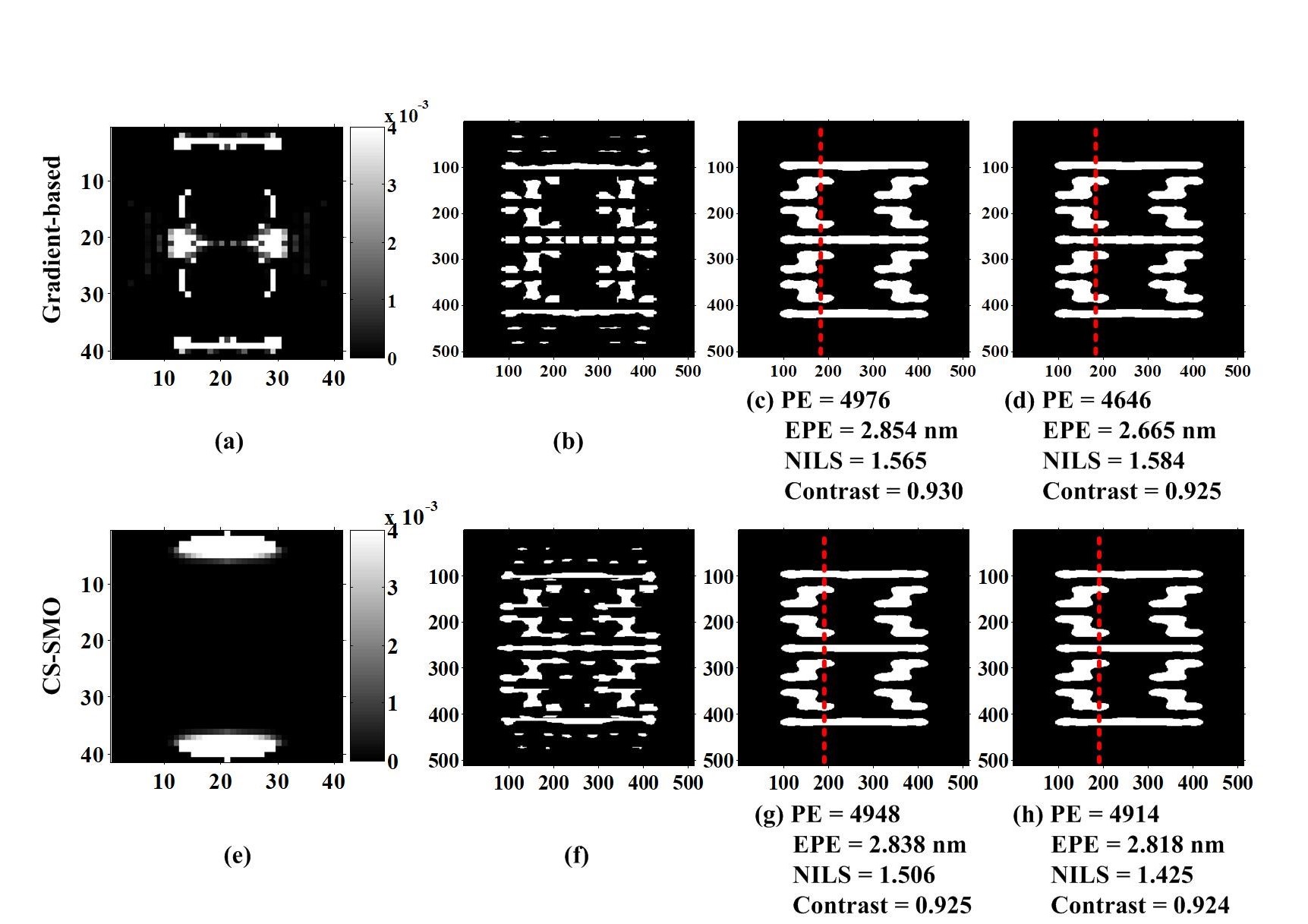
Figure 2 illustrates the simulations based on a dense line-space layout pattern with CD = 45nm. The first row illustrates the simulation using the initial source pattern and initial mask pattern. The second row shows the result obtained by the traditional gradient-based SMO algorithm proposed in Reference [9]. In the traditional hybrid SMO algorithm [9], the source pattern is firstly individually optimized, and then the mask pattern is individually optimized. Finally, the source and mask patterns are simultaneously optimized for several times. The third row illustrates the simulation of the proposed CS-SMO algorithm. From left to right, it respectively shows the source patterns, mask patterns, and the print images on the focal plane and defocus plane. The values of pattern error (PE), edge placement error (EPE), normalized image log slop (NILS) and aerial image contrast are used as the metrics to assess the lithography imaging performance. The NILS and aerial image contrast are measured along the red dotted line in the figures. In this simulation, the SO problem is solved by the LB algorithm. The runtime of the traditional gradient-based SMO algorithm is about 214,695s. On the other hand, the runtime of the proposed CS-SMO algorithm is about 39,945s. It is noted that the runtime should be changed with the computational resources used and the scale of the layout patterns. It is observed that proposed CS-SMO algorithm will results in better imaging performance than the traditional gradient-based SMO algorithm, and speed up the computational efficiency by 81% as well.


Figure 2.   
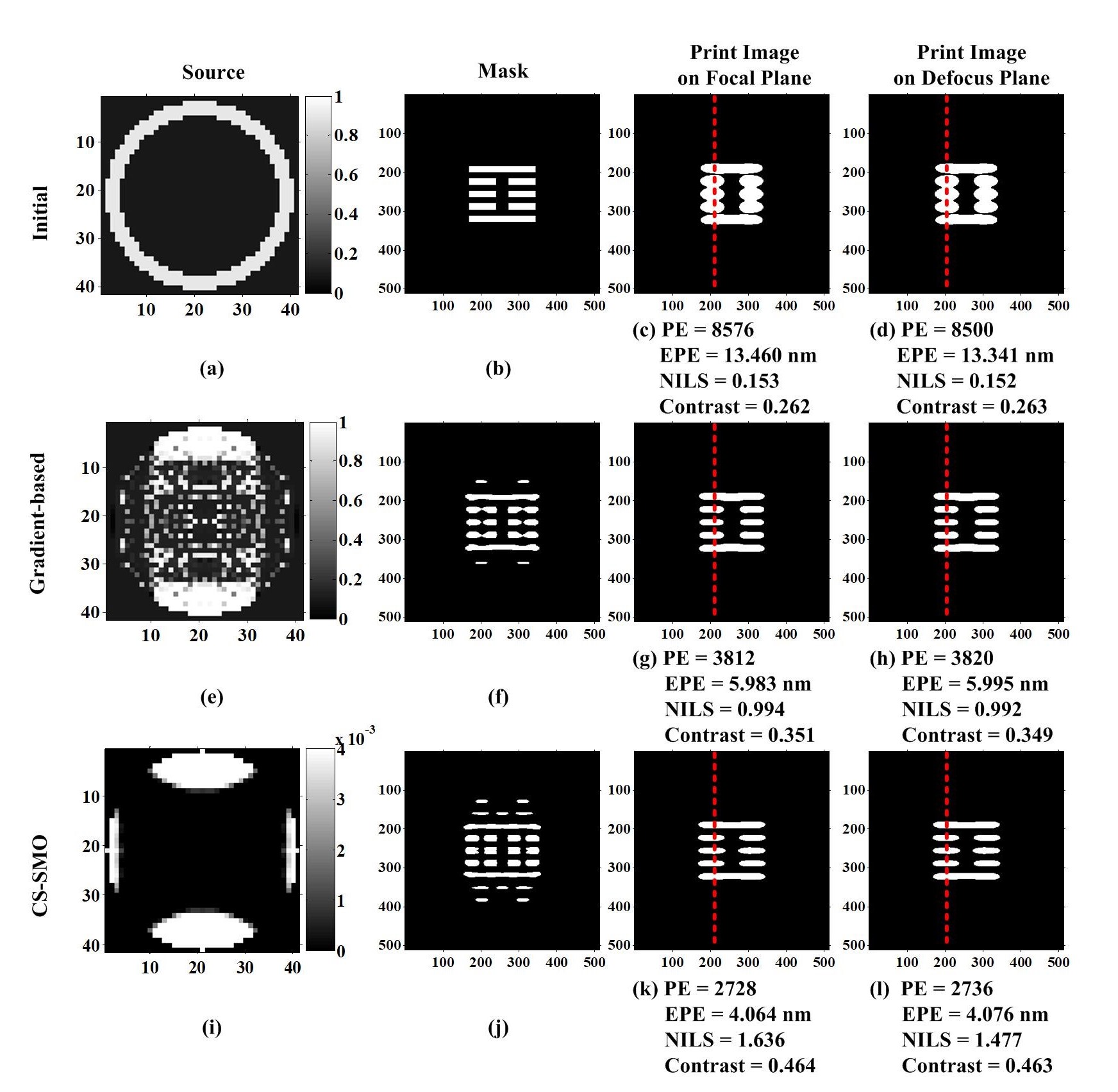
Comparison of CS-SMO and gradient-based SMO algorithms using a vertical line-space pattern.
Figure 3 uses another horizontal block pattern to run the simulations of the CS-SMO and gradient-based SMO algorithms. In this simulation, the SO problem is solved by the LB algorithm. The runtimes of the traditional gradient-based SMO algorithm and the proposed CS-SMO algorithm are 214,485s and 25,243s, respectively. The simulation results in Figure 3 also proves the superiority of the proposed CS-SMO algorithm over the traditional gradient-based SMO algorithm in terms of the imaging performance and the computational efficiency.


Figure 3.   Comparison of CS-SMO and gradient-based SMO algorithms using a horizontal block pattern.
In Figure 4, we assess the proposed CS-SMO method based on a complex layout pattern. The first row shows the simulation of the traditional gradient-based SMO algorithm. The second row shows the simulation of the proposed CS-SMO algorithm, where the GPRS algorithm is used to solve for the SO problem, and the MO problem is still solved by the IHT algorithm. The NILS and aerial image contrast are measured along the red dotted line in the figures. The runtimes of the traditional gradient-based SMO algorithm and the proposed CS-SMO algorithm are about 214,610s and 13,143s, respectively. Compared to the traditional gradient-based SMO algorithm, the CS-SMO algorithm is more efficient, and achieves higher image fidelity of the lithography system.


Figure 4.   Comparison of CS-SMO and gradient-based SMO algorithms using a complex layout pattern.
5.   Conclusion
This paper developed an efficiently SMO method based on CS framework. The CS-SMO model was established based on the Abbe’s imaging model of the lithography systems. The downsampling method on the layout pattern was used to reduce the dimensionality of the SMO problem. The proposed CS-SMO algorithm was implemented by alternately carrying out the individual SO and individual MO stages. The sparse image reconstruction algorithms were used to obtain the optimal source and mask patterns based on the sparsity regularization. It shows that the proposed CS-SMO method outperforms the traditional gradient-based SMO algorithm in terms of both computational efficiency and lithography imaging performance.
Acknowledgments
We thank for the financial support by the National Natural Science Foundation of China (NSFC) (61675021), and the Fundamental Research Funds for the Central Universities (2018CX01025).
[1] Y. Wei, Advanced Lithography Theory and Application of VLSI, Science Press, Beijing (2016).
[2] A. K. Wong, Resolution Enhancement Techniques in Optical Lithography, SPIE (2001).
[3] X. Ma and G. R. Arce, Computational Lithography, Wiley Series in Pure and Applied Optics, 1st ed., John Wiley and Sons (2010).
[4] A. E. Rosenbluth, S. Bukofsky, C. Fonseca, M. Hibbs, K. Lai, A. Molless, R. N. Singh, and A. K. Wong, “Optimum mask and source patterns to print a given shape,” J. Microlith. Microfab. Microsyst.1 (1), 13-30 (2002).
[5] A. Erdmann, T. Fühner, T. Schnattinger, and B. Tollkühn, “Towards automatic mask and source optimization for
optical lithography,” Proc. SPIE5377 , 646–657 (2004).
[6] X. Ma and G. R. Arce, “Pixel-based simultaneous source and mask optimization for resolution enhancement in
optical lithography,” Opt. Express17 (7), 5783–5793 (2009).
[7] M. Guo, Z. Song, Y. Feng, Z. Tian, Q. Cao, and Y. Wei, “Efficient source mask optimization method for reduction of computational lithography cycles and enhancement of process-window predictability,” J. Micro/Nanolith. MEMS MOEMS14 (4), 043507 (2015).
[8] X. Wu, S. Liu, J. Li, and E. Y. Lam, “Efficient source mask optimization with Zernike polynomial functions for source representation,” Opt. Express22 (4), 3924-3937 (2014).
[9] X. Ma, C. Han, Y. Li, L. Dong, and G. R. Arce, “Pixelated source and mask optimization for immersion lithography,” J. Opt. Soc. Am. A30 (1), 112–123 (2013).
[10] C. Yang, S. Li, and X. Wang, “Efficient source mask optimization using multipole source representation,” J. Micro/Nanolith. MEMS MOEMS13 (4), 043001 (2014).
[11] Y. Shen, “Lithographic source and mask optimization with narrow-band level-set method,” Opt. Express26 (8), 10065-10078 (2018).
[12] D. Donoho, “Compressed sensing,” IEEE Trans. Inform. Theory52 (4), 1289-1306 (2006).
[13] E. Candés, J. Romberg, and T. Tao, “Robust uncertainty principles: Exact signal reconstruction from highly
incomplete frequency information,” IEEE Trans. Inform. Theory52 (2), 489-509 (2006).
[14] L. Galvis, H. Arguello, and G. R. Arce, “Coded aperture design in mismatched compressive spectral imaging,” Applied Optics54 (33), 9875-9882 (2015).
[15] X. Ma, D. Shi, Z. Wang, Y. Li, and G. R. Arce, “Lithographic source optimization based on adaptive projection compressive sensing,” Opt. Express25 (6), 7131-7149 (2017).
[16] X. Ma, Z. Wang, H. Lin, Y. Li, G. R. Arce, and L. Zhang, “Optimization of lithography source illumination arrays using diffraction subspaces,” Opt. Express26 (4), 3738-3755 (2018).
[17] X. Ma, Z. Wang, Y. Li, G. R. Arce, L. Dong, and J. G. Frias, “Fast optical proximity correction method based on nonlinear compressive sensing,” Opt. Express26 (11), 14479-14498 (2018).
[18] S. Osher, M. Burger, D. Goldfarb, J. Xu, and W. Yin, “An iterative regularization method for total variation-based image restoration,” Multiscale Model. Simul.4 (2), 460-489 (2005).
[19] J. F. Cai, S. Osher, and Z. Shen, “Linearized bregman iterations for compressed sensing,” Mathematics of Computation78 (267), 1515-1536 (2009).
[20] Figueiredo, M. A. T., Nowak, R. D. and Wright, S. J., “Gradient projection for sparse reconstruction: application to compressed sensing and other inverse problems,” IEEE Journal of Selected Topics in Signal
Processing1 (4), 586-597 (2008).
[21] T. Blumensath, “Compressed sensing with nonlinear observations and related nonlinear optimization problems,” IEEE Trans. Inf. Theory59 (6), 3466–3474 (2013).
Article and author information
Xu Ma
Zhiqiang Wang
Gonzalo R. Arce
Publication records
Published: Dec. 13, 2018 (Versions3
References
Journal of Microelectronic Manufacturing