Research Article Archive Versions 3 Vol 1 (1) : 18010104 2018
Download
Analysis of Current Research Status of Plasma Etch Process Model
: 2018 - 09 - 01
: 2018 - 09 - 30
2933 63 0
Abstract & Keywords
Abstract: This paper summarizes the status of the plasma etch process modeling research. It mainly introduces typical etching models employing the analytical method, geometric method, system identification method, basic principle simulation method, as well as empirical model. Each model’s basic principles, application scopes, advantages and disadvantages are discussed. Based on these, the development history of the etch process modeling is summarized, and the development opportunities of the etch model are prospected. This paper provides a brief view for establishment of the plasma etching process model.
Keywords: plasma etching; etching model; simulation
1.   Introduction
Plasma etching play an important role in the integrated circuit (IC) manufacturing process, and many models have been developed to date for simulating etching processes[1] ,[2],[3],[4],[5]. Plasma etching has been widely used, however its reaction mechanism is very complicated, partially because the process conditions and parameter settings are difficult. Therefore a few different plasma etching models have been developed to better understand the plasma etching process, reduce the expensive experimental burden and accelerate the development of large-scale etching reactors. There are five main ideas for the establishing plasma etching models. The first one is the analytical method that uses mathematical equations, including the surface dynamics model, micro-surface reaction model, continuous CA model, and Wulff-Jaccodine plotting method. The second one is the geometric method using feature process parameters or models, it mainly includes the Monte Carlo model, particle grid method, and hybrid model that combines both. The third one is a system identification method using a neural network model, which mainly includes a BP-based neural network mode. The fourth one is a method based on the basic principle of establishing a plasma etching model, which mainly includes a mixed plasma model named two dimensional and three dimensional hybrid plasma equipment model (2D-HPEM and 3D-HPEM), a 2D and 3D modular plasma reactor simulator (2D-MPRES and 3D-MPRES). The last one is the empirical model, which is also known as the black box model.
In this paper, we review the research progress of the plasma etching model. The above five modeling methods and their main models are discussed. The advantages, disadvantages, application scope and development prospect of each model are summarized.
2.   Etching Model
The etch model is a process used to describe the surface etching or adsorption process. The creation of the etch model is based on the plasma. Firstly, the complex physical and chemical reactions in the etching process, along with the interaction of different neutral particles and charged particles (electric field, flow field, force field, etc.), make it difficult to describe the plasma etching process. Secondly, the plasma etching process model needs to consider the process requirements corresponding to the increasing size of the chamber and the shrinking device size. Therefore, although plasma etching equipment has been widely used in the integrated circuit manufacturing industry, an effective method for completely simulating and analyzing the plasma etching process in theory has not been developed.
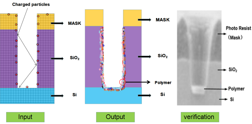
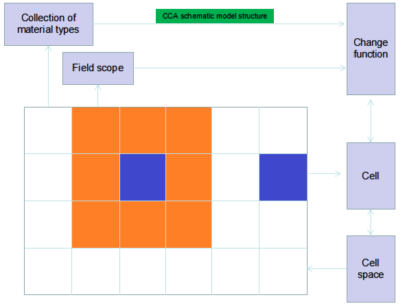
As shown in Figure 1, an etch model is created. First of all, a mathematical model of the surface feature profile is established based on the characteristics of the etching process. Then thenumerical simulation is carried out. Meanwhile the experimental conditions are selected according to the mathematical model, the silicon wafer experiment is carried out, the simulation values are fitted with the experimental values, and the mathematical model established in the previous stage is calibrated. Finally, the mathematical model and optimization algorithm are combined to improve the prediction accuracy and effectiveness of the etch model.


Figure 1.   
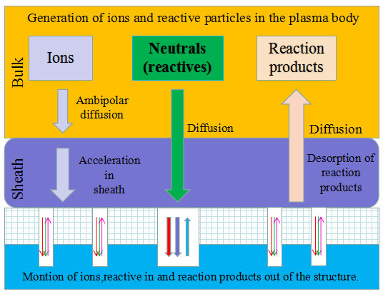
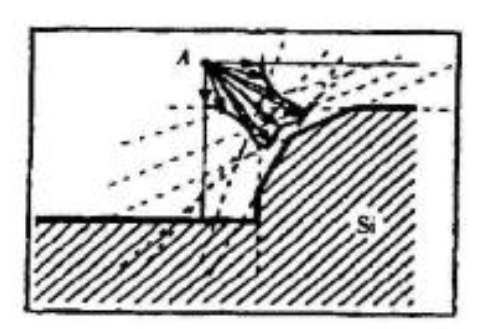
Schematic diagram of the establishment and verification of the etching model.
The etching process is to transfer the photolithographic pattern onto the film on the surface of the silicon wafer. The photoresist is used to cover the wanted area while exposing the unwanted area by chemical reaction or physical reaction to complete the pattern transfer. The plasma etching is a plasma-based process and is the most widely used dry etching method. It is a general term for etching all available plasmas. The most common etching methods are reactive ion etching (RIE), inductively coupled plasma (ICP) etching, and capacitively coupled plasma (CCP) etching, etc. The chemical etching and physical etching are the two major methods in the plasma etching process, however the physical etching accounts for a small proportion. As shown in Figure 2, the plasma etching occurs in the reaction chamber. The gas is introduced into the chamber and plasma is generated during the glow discharge. By applying the accelerating electric field perpendicular to the silicon wafer, a large amount of electrons are perpendicularly colliding on the surface of the silicon wafer, and part of the kinetic energy is dissipated by the physically etching, and the remaining energy leads to the surface chemical reactions forming a volatile product, which is eventually pumped away by the vacuum system. The "reaction-peel-discharge" is repeated, and the surface of the material is gradually etched to a specified depth.


Figure 2.   Basic mechanisms.
2.1.   Establishing Factor of Etching Model
Due to the complexity of the etching process, the process conditions and parameters are difficult to set up, the process involves the intersection of microfluidics, micro-heat transfer, molecular dynamics and other disciplines.
The establishment of a perfect etching model requires consideration of various factors, including the process condition variations, corrosion interface reactions, external environment impact on the corrosion process, and the process equipment influence[6].
2.2.   Etching Model Description Object
The etching process is described mainly three aspects: material characteristics, structural features and process characteristics.
2.3.   Method for Establishing Etching Process Model
The best approach is to start building the model from a simple one. From the physics point of view, it is preferred to assume a simple reactor shape, a single excitation method (RIE, CCP, ICP, ECR, etc.), and, a limited species of gas. Then continue to increase the parameters to optimize the model. The current etch model modeling cannot achieve good versatility because whenever the gas changes, the shape of the reactor changes or a different excitation mode is selected, the mechanism of the entire etch is changed, resulting in different etching models. The current modeling methods are as follows: (1) analytical method: this model explains the reaction mechanism and factors involved in the process and their influence on the corrosion process in the form of mathematical equations, it obtains the required parameters as input and output results by equation calculations; (2) geometry method: based on the geometric model, the feature process parameters or feature process models are used to obtain the output of the three-dimensional model through feature recognition; (3) system identification method: the neural network model is applied to establish a non-linear mapping relationship between input and output to predict the process result; (4) basic principle simulation method: based on the basic principle, a plasma etching model is established, which involves the continuity in the high-frequency, high-intensity electric field, the beam balance and the energy balance equation; (5) empirical model: in this case the basic physical process is largely ignored, and the problem is only parameterized from the perspective of actual process behavior. A mathematical model is established by analyzing how the input measurement projects to the output measurement.
3.   Research Status of Etching Model
The etching process model is mainly used to predict the shape after etching before the experiment, and the experimental conditions can be theoretically optimized at the early stage. The etching process model is established according to different process conditions using geometric method, analytical method, system identification method or basic principle simulation method. Several methods can also be applied comprehensively[7] ,[8]. Followings are a few the typical models under these abovementioned methods.
3.1.   Surface Dynamics Model
The surface dynamics model is obtained by solving the dynamic equations and obtaining the particle distribution function. The ion or neutral particle flow, ion energy, angular distribution and other parameters are used to calculate the etching or deposition rate, product stoichiometry, surface coverage, etc.
The main research objects of surface dynamics are physical mechanisms and processes. The model requires a comprehensive analysis of various factors, description of process conditions and reaction processes, and calculation of etch rates. Surface dynamics models need to involve multidisciplinary knowledge, and for specific condition, it is also necessary to clarify the reaction mechanism, and the calculation is also challenging[9].
Commonly used surface kinetic models are divided into reaction site model, molecular dynamics model, and mixed layer dynamics model.
3.1.1 Reaction Site Model
The reaction site model assumes that the molecules of a single layer are adsorbed on the surface, and the reaction mechanism is simplified by a series [10] ,[11],[12],[13],[14],[15]. Based on the Langmuir-Hinshelwood (L-H) mechanism, the surface reaction is used as a control step, and the heterogeneous catalytic mechanism of the surface reaction of two adsorbed molecules[16]. The expression of the surface composition and the etch rate are derived by using the mass balance equation of the particles entering or leaving the surface region[17] ,[18],[19],[20],[21]. However, the reaction mechanism under this model is relatively simple, which will have a great influence on the final simulation results, and the more complex the reaction process, the bigger the result deviation will be. The model can not consider etching and deposition simultaneously. When there are many kinds of plasma in this model, each plasma can not be simulated. All in all, this model belongs to the earlier model, and it is not suitable for complex simulation.
3.1.2.   Molecular Dynamics Model
A molecular dynamics model is a motion simulation of a collection of particles, including atoms, molecules, or some other specific particles. In this model each particle is simulated reacts through the potential between the atoms, and the surface potential energy surface of the entire system is obtained by analyzing all the reactions in the system. The reaction between the plasma and the surface was simulated from the point of view of physics by the molecular dynamics model. The central problem of this model is that it is difficult to accurately determine the potential between atoms. The potential energy equation requires a lot of parameters, and it is difficult to obtain these parameters accurately. Finally, the etching products are formed too fast, the simulated etch product formation time is around 1 ps, which is much shorter than the actual chemical reaction time which generally 1 ms [22] ,[23],[24],[25].
3.1.3.   Mixed Layer Dynamics Model
The mixed layer kinetic model is equivalent to the reaction site models. It assumes that there is a sufficiently uniform mixed layer between the plasma and the substrate as the foremost end of the etching. The advantage of this method is that the uniformly mixed atoms in the mixed layer and their adjacent bonding probability can be used to define the concentration of chemical components including different reaction mechanisms of different reaction products, and the mixed layer model introduces a time-varying difference equation. The thickness of the mixed layer is constant[26] ,[27],[28],[29],[30],[31]. This model can integrate almost all the reactions in the etching process, including ion incorporation, particle adsorption, physical sputtering, ion assisted etching, space generation and extinction, and spontaneous etching. Compared with the reaction site model, the mixed layer kinetic model has the advantage of more accurate calculation of the chemical reactions occurring between the plasma and the surface, so this model is more suitable for complex reaction systems. At the same time, the comparison between the model and the molecular dynamics model shows that the calculation of the model is small, the idea of modeling is simple, the model has good reusability, and the simulated results are in good agreement with the experimental results.
3.2.   Infinitesimal Reaction Surface (IRS) Model
The Infinitesimal reaction surface model outlines the surface reaction by adsorbing the particle layer on the surface of the substrate. It analyzes the particle coverage on the particle flow and the etched section. By describing the macroscopic particle adsorption layer on the surface of the substrate, the coverage of the etched surface in terms of time is calculated to make the etch simulation more precise.
As shown in Figure 3, several different particles are transported and adsorbed on the etched surface during the etching process. ASK is assumed to represent the surface coverage of the adsorbed particles k, and ES is the surface coverage of the clean regions without the ions. Different reactions occur on the surface where different particle coatings are present. Ion-assisted etching will occur in the surface region covered with reactive particles. In the surface region covered with non-reactive particles, a deposition reaction will occur. In the clean portion where the coverage is ES, a sputtering reaction will occur. By doubling the coverage of each particle with the reaction rate at which the reaction may occur, followed by summing it up, the etch rate of the entire local region can be obtained[32]. Based on the obtained etch rate, the surface evolution algorithm can be used to derive the etching process. However, this method has certain difficulties in calculating the coverage of each particle in different regions.
This model includes four basic surface reaction mechanisms[56]: (1) thermally induced chemical reaction: the reactive group is transported to the surface of the substrate and adsorbed, and the reaction product is driven away by the thermal energy of the substrate; (2) two types of ion sputtering: the physical sputtering the substrate atoms gains energy through the momentum transfer of the incident stream yields and get struck out of the surface, and the chemical sputtering incident ions induce chemical reactions that form desorption of particles; (3) ion-assisted etching: a process in which reactive ion adsorption and energy ion bombardment coexist, and the etching yield is high; (4) adsorption of non-reactive groups: it leads to deposition of polycrystalline silicon, and the adsorption of non-reactive groups has an inhibitory effect on the etching process.
The main research object is the reaction mechanism and process. The model focuses on the etching principle and process and quantitatively analyzes the reaction mechanism. The establishment of such a model requires multidisciplinary knowledge, and for specific conditions, it is necessary to clarify the reaction mechanism, which is very difficult to calculate[16].


Figure 3.   Infinitesimal reaction surface (IRS)[32].
3.3.   Continuous Cellular Automaton Model
There are four cellular automaton(CA) models, namely cellular automata, stochastic CA model, continuous cellular automaton and dynamic CA algorithm based on time compensation[33] ,[34],[35]. The following part mainly introduces the cellular automaton and continuous cellular automaton which are widely used.
The main research object of this model is the etching process and contour evolution. This model class is applied to any complex two-dimensional three-dimensional structures, and simulate various types of etching and materials to achieve high-precision and high-efficiency simulation. However, as the simulation intensity improves, the simulation efficiency will decrease[16].
CA is a dynamic system with discrete space and time. The cell is used to describe the current state of the relevant spatial location. It defines the spatial evolution rule based on the neighboring environment for each cell by defining spatial evolution rules in discrete time dimensions. It uses the cell array in the crystal grid to describe the base material, determine the connection state between adjacent cells, and determine the rules for the current cell movement [36]. The key to this model is the determination of the movement rules and etch rate. Discrete cell arrays can simulate any complex mask patterns, however since each cell in the grid can only be in one of the "removed" or "retained" state, it cannot reflect the true etch rate on different crystal faces. Therefore, this model’s simulation accuracy is relatively low.
The random CA model uses random elements to describe the true etch rate on different crystal planes and can be used to process any etch rate on the main lattice axis. However, this artificially causes the surface to be rough, making the edges and planes difficult to distinguish, and it is not convenient to directly observe the simulation results.
Continuous CA model allows the cells in the system to have non-discrete state variables, the range of values is [0, 1], and it allows for any etch rate in the direction of the main axis, avoiding artificially roughening the surface and improving analog accuracy. The cell mass M is its non-discrete state variable. It can be assumed that any state of a cell is between M=0 (etched) and M=1 (without etching), and the value of M is related to the cell’s movement trend. Based on the active cell movement rule in the non-discrete element state, the prediction of three-dimensional shape under arbitrary etchant and etch rate conditions can be realized [37] ,[38]. In the continuous cellular automaton (CCA), the occupancy rate for representing the cell state is continuous during the update iteration, which further enhances the applicability and accuracy of the CA method. The CCA model and the calculation flow are shown in the Figure 4 and Figure 5.


Figure 4.   CCA schematic model structure.


Figure 5.   CCA model calculation flow chart
Later on, in order to reduce the memory requirements of this algorithm, a dynamic CA algorithm based on time compensation was developed. This algorithm improves the simulation speed and lowered the memory requirement. And it can be used to simulate the entire process flow results with several sequential processing steps.
3.4.   Wulff-Jaccodine Drawing Method
The Wulff-Jaccodine plotting method is based on the etch rate database and is the core of the three-dimensional anisotropic etching simulation system[38] ,[39]. The method is suitable for a single crystal multi-step anisotropic etching process or an out-of-body anisotropic etching process of any initial shape. The etch profile under the algorithm is determined by the set of vertical lines that minimize surface energy shown in Figure 6. Suppose that the outline is a polygon, and each side of the polygon moves at a respective etch rate, which is related to the crystal orientation of the edge; use the Wulff-Jaccodine plotting method to determine the geometrical variation of the intersection of two adjacent edges or the edge of the masked area. Consider the etch velocity vector between two adjacent planes at point A where these vectors have a common origin, the assumed etched surface is drawn at the end of the vector and perpendicular to it, and the exact etch profile is determined by these sets of perpendiculars that minimize surface energy. The simulation program calculates the profile change at each step of the three-dimensional etch in a predetermined time increment. The calculated profile is checked at each step of etching about; whether there is a plane disappearing or a new plane is generation, and once there is a change in the plane set, the calculation is updated by the new set. The method is suitable for a single crystal multi-step anisotropic etching process or an out-of-body anisotropic etching process of any initial shape, and can realize prediction of complex contours such as micro impellers.


Figure 6.   Wulff-Jaccodine analytical method[6]
The model focuses on the etching process and contour evolutions, and can be applied to 3D simulation, anisotropy, single crystal, but except for polycrystalline [16].
3.5.   Monte Carlo Model
The Monte Carlo (MC) model is based on two methods, namely the Monte Carlo method and dynamic Monte Carlo method. The Monte Carlo method is an effective method to replace the actual experimental process with mathematical simulation. The kinetic Monte Carlo method (KMC) is a numerical method that does not directly solve equations by particle simulation. The result is the position and velocity of the particles, so that a series of required parameters can be directly obtained.
This model focuses on the particle reaction process. Suitable for studying output geometry and modular structures, but with a large amount of computation.
As shown in Figure 7, in the Monte Carlo model[38] ,[40],[41],[42], a finite set of particles is used to represent the entire particle swarm. The statistical nature of a particle is simulated by letting a series of processes occur randomly, for example, the particle is generated or dissipated via an elastic or inelastic collision, and the average probability is to follow the practical frequency of occurrence. This method relies on the corresponding basic concept that the particle motion follows Newton's law and the probability. To ensure the accuracy of this method, a sufficient collection of particles is needed. Today, there are multiple models that can handle millions of particles. Obviously, integrating so many particles into one list is not suitable for people to use, there the Monte Carlo method requires a subsequent process to convert the raw data into the average status of the particles, usually they are functions of the particle position


Figure 7.   Cellular realization of the kinetics modeling in 3D Monte Carlo profile simulator.
3.5.1.   Particle Grid-Monte Carlo Method
The particle in cell (PIC) method is a finite particle method for simulating multi-component plasmas and particle beams[43] ,[44],[45],[46]. It is a powerful tool for the numerical simulation of continuum, space and plasma dynamics. The basic idea of plasma particle simulation is to set a large number of charged particles with initial position and velocity, calculate their movement, find the charge and current density distribution of the plasma space, and then determine the electric and magnetic fields everywhere through Maxwell's equations. Then the Lorentz force of each particle is obtained, and the position and velocity of each particle at the next moment can be obtained by the motion equations. During this cycle, the motion of a large number of charged particles are tracked and calculated, and then some physical parameters of these large charged particles are counted according to the problem of interest, and the material properties and motion processes of the macroscopic plasma can be obtained.
The Particle Grid-Monte Carlo Method (PIC-MC) is a standard method used to simulate etching or depositing plasma reactors. As shown in Figure 8, a large number of charged particles are preset with an initial position and velocity, and the motion trajectory is calculated by the law of motion to obtain a collision process. The charge distribution is calculated by considering the positional weighting of all the particles, and the distribution of the electric field is calculated by the Poisson equation of each grid point.


Figure 8.   Schematic diagram of method PIC-MC[43].
3.5.2. Monte Carlo Model of Hybrid Evolutionary Algorithm
The simulation process of the Monte Carlo model of the hybrid evolutionary algorithm first provides some inaccurate and random initial parameters, this is followed by automatically calibration of the MC model, then converges achieve correct energy parameters. Finally, different etch conditions are optimized to obtain corresponding parameters[38].The advantage of this method is that it can automatically obtain the energy parameters of the Monte Carlo method based on the atomic model, and enhance the simulation ability. The calculation flow chart of the Monte Carlo model of the hybrid evolution algorithm is shown in Figure 9.


Figure 9.   Monte Carlo model of the hybrid evolution algorithm.
3.6.   BP-based Neural Network Model
The neural network model based on BP algorithm is obtained through the experimental research on reactive ion etching process based on the segmentation fitting optimization by Lu Jianzu et al. It can be used to predict the dry etching rate and aspect ratio at fixed RF power and gas flow[47].
This model mainly focuses on the process parameter solving and system input and output relationships. It considers the process as a whole, and it can combine with the equipment simulation model, which is suitable for multiple input and output, nonlinear and diversified process conditions. However, the accuracy of this model needs to be improved, and it is impossible to accurately predict the change of material properties during the process[16].
3.6.1.   Hybrid Plasma Equipment Model (HPEM)
The simulation and verification of the hybrid plasma device model were originally developed for two dimensional conditions, and the prerequisite for its use is the need to define the reactor shape and initial operating conditions[7] ,[48],[49],[50],[51],[52]. HPEM uses the Maxwell equation to solve the electromagnetic module (EMM).Based on the electromagnetic field obtained from the EMM, the electron density, electron temperature, electron energy distribution function, and electron collision reaction rate were calculated using the Monte Carlo program in the electron energy transfer module (EETM).The heavy particle density and flow rate are then calculated using the continuity equation in the fluid dynamics simulation (FKS), and the Poisson equation is used to calculate the electromagnetic field, which is used as the input value for the next cycle EMM. This cycle is repeated until convergence. Plasma chemistry Monte Carlo simulation is used as an optional module to calculate the plasma ion flux and energy distribution to the sinker. This HPEM is primarily concerned with the distribution of plasma in various reactors such as ME-RIE, CCP, ICP. Later on, HPEM was extended to a three-dimensional (3D) version.
It was found that in 2D-HPEM, the etching rate was greatly affected by the energy and flow rate of ions striking the substrate, and was less affected by the value of the radical flow rate, even if the radical flow rate was greater than 100 times the total ion flux.
3.6.2. Modular Plasma Reactor Equipment Simulator (MPRES)
The University of Houston's Lymberopoulos and Economou (1995) developed the 2D Modular Plasma Reactor Simulator (MPRES) for ICP reactors[7] ,[53]. The simulator contains complex plasma reactions that involves electrons, ions and neutrals, and surface reactions. Panagopoulos and Economou (1999) provided a three-dimensional version of MPRES to examine the azimuthal asymmetry of etch uniformity during etching of polysilicon wafers with chlorine plasma in an ICP reactor. MPRES-3D can perform self-consistent simulations of gas phase and surface chemistry in any three-dimensional ICP reactor. Its finite element mesh is generated by FEMAP (commercial software package), which is a general purpose grid generator. The analog input section includes the geometry of the reactor, the structural materials of the reactor, operating conditions, transport characteristics of the ions of interest, and chemical kinetics. The MPRES-3D contains five modules. The simulator first solves the Maxwell equation in the "electromagnetic module" to determine the distribution of plasma power deposition under given electromagnetic field and operating power. The output is fed back to the "electronic energy module" for the calculation of the electron temperature and electron collision reaction rate coefficients. These two results are the input to the "charged particle reaction and transport module" for the calculation of the electron temperature and electron collision reaction rate coefficients. These two results are input into the "charged particle reaction and transport module" and "neutral particle reaction and transport module", the former provides the density of charged particles, while the latter calculates the neutral gas composition. This loop will be iterated until it "converges." Finally, the convergent solution can provide self-consistent power deposition, electrostatic potential, electron temperature, charged particle and neutral particle density, etch rate, uniformity, and selectivity on the wafer surface. The "sheath module" is typically used as a post-processing step to calculate the time-dependent plasma, the potential on the back wall of the substrate, the DC bias formed on the wafer electrode, and the energy distribution of the particles as they bombard the surface of the wafer.
3.7.   Empirical Model
The empirical model, also known as the black box model[7]. Due to the actual simulation of a particular reactor, the required solution time is approximately half an hour, which is unacceptably slow for process control that may require real-time feedback. In addition, the lack of a basic understanding of the complex interactions of target materials and etching gases often misleads simulation results. Although the empirical model relies purely on experimental data, lacking a deep understanding to the principles, and is limited to the range of available data, it may be easier to be applied in practical manufacturing. Due to the abovementioned it is necessary to make a compromise between these two aspects.
The mainstream of the dry etch process experience model focuses on the use of limited experimental data or routine production data verification, while the latter is not the favored choice due to the lack of "activity" that ensures the reliability of the verification model. In addition, black box modeling is difficult which requires the ability to predict the spatial distribution index simply by conventional batch or single point measurements. Therefore, the alternative is to use a basic principle-based simulator to provide a reliable basis for the development of reduced-order mathematical models, which is attractive at least at the initial stages of actual device manufacturing.
Empirical model is a relatively feasible model at present. Combining theory with practice reduces the complexity of theoretical analysis to a certain extent. Combining with experimental data will also increase the accuracy of simulation. Summarizing the model described in this article, table 1[54] ,[55],[56],[57],[58],[59],[60],[61],[62].
Table 1.   Etching method.
Research methodsModel nameResearch methods and objectsFeatures and applicable occasionslimitation
Analytical methodSurface dynamics modelSimulated physical processComprehensive analysis of various factors; description of process conditions and reaction mechanism; calculation of etch rateMultidisciplinary knowledge; specific conditions; clear reaction mechanism; difficult to calculate
Infinitesimal reaction surface (IRS) modelSimulated reaction mechanism and processDescribe the etching principle and process; quantitative analysis of the reaction mechanism
Continuous CA modelSimulated etching process and contour evolutionArbitrary complex two-dimensional, three-dimensional structure; simulate various types of etching and materials; achieve high-precision, high-efficiency simulation’As the simulation accuracy increases, the simulation efficiency decreases.
Wulff-Jaccodine drawing methodSimulated etching process and contour evolution3D simulation; anisotropic, single crystalNot suitable for polycrystalline
Geometric methodMonte Carlo modelSimulated particle reaction processOutput geometry; modular structureLarge amount of calculation
System identification methodBP-based neural network modelProcess parameter solving, describing system input and output relationshipsConsider the process as a whole; obtain the process simulation model of the equipment; suitable for multiple input, multiple output, nonlinear and diversified process conditionsAccuracy needs to be improved; it is not possible to accurately predict changes in material properties during the process
Basic principle methodHybrid plasma equipment modelSimulated reaction mechanism and processArbitrary complex two-dimensional, three-dimensional structure; simulate various types of etching and materialsFocus only on the distribution of ions in a reactor; ignore the effects of free radical flow values
Modular Plasma Reactor equipment SimulatorSimulated reaction mechanism and processArbitrary complex two-dimensional, three-dimensional structure; simulate various types of etching and materials; achieve high-precision, high-efficiency simulationOnly for ICP reactors
Empirical modelSimulated etching process and contour evolutionCombine actual process parameters with theoretical modelsNeed regular experimental data prediction results
4.   Conclusion
The etch process model can be established according to different process conditions and research objects, including geometric method, analytical method, system identification method, basic principle simulation method and empirical model. These methods can also be applied comprehensively. When establishing the etching process model, the influence of process conditions, process variations, physical and chemical reactions occurring at the interface, and equipment impact should be considered. In order to improve the simulation accuracy, the influence of various factors should be comprehensively analyzed in the etching model, and some parameters in the simulation model should be calibrated.
The etching process development is very expensive and time consuming, a reliable simulation model helps to precisely predict the process results and therefore reduce the development risk and cycle time, improving the yield.
Acknowledgement
This work was supported by Beijing Natural Fund 4182021. We are grateful to the Academy of Electronic Information Engineering of North China University of Technology (NCUT) for financial support and the Key Laboratory of Microelectronics Devices and Integrated Technology, Institute of Microelectronics, Chinese Academy of Sciences for advising.
[1] J. P. Chang, J. C. Arnold, G. C. H. Zau, H. S. Shin, et al., “Kinetic study of low energy argon ion-enhanced plasma etching of polysilicon with atomic/molecular chlorine,” J. Vac. Sci. Technol. A,15 , 1583 (1997).
[2] J. W. Coburn, “Role of ions in reactive ion etching,” J. Vac. Sci. Technol. A,12 , 1417 (1994).
[3] J. W. Coburn, “Chlorine‐enhanced F‐atom etching of silicon,” J. Vac. Sci. Technol. A,12 , 617 (1994).
[4] G. S. Oehrlein, M. F. Doemling, B. E. E. Kastenmeier, P. J. Matsuo, et al., “Surface science issues in plasma etching,” IBM J. Res. Dev.,43 , 181 (1999).
[5] M. Schaepkens, I. Martini, E. A. Sanjuan, X. Li, et al., “Gas-phase studies in inductively coupled fluorocarbon plasmas,” J. Vac. Sci. Technol. A,19 , 2946 (2001).
[6] X. Yu, “Dynamics model and 3D simulation of plasma etching,” Southeast University (2015).
[7] Y. Zhang, “Nano-integrated Circuit Manufacturing Process - 2nd Edition,” (Tsinghua University Press, Beijing, 2017).
[8] X. Wu, and G. Li, “Simulation Method and Analysis of Typical Micromachining Etching Process,” Machinery Manufacturing,11 , 23 (2004).
[9] W. Jiang, “Research and Simulation of MEMS Etching Process Model,” Nanjing University of Posts and Telecommunications (2016).
[10] R. A. Barker, T. M. Mayer, and W. C. Pearson, “Surface studies of and a mass balance model for Ar+ ion‐assisted Cl2etching of Si,” J. Vac. Sci. Technol. B,1 , 37 (1983).
[11] D. J. Cooperberg, V. Vahedi, and R. A. Gottscho, “Semiempirical profile simulation of aluminum etching in a Cl2/BCl3plasma,” J. Vac. Sci. Technol. A ,20 , 1536 (2002).
[12] E. Gogolides, P. Vauvert, G. Kokkoris, G. Turban, et al., “Etching of SiO2 and Si in fluorocarbon plasmas: A detailed surface model accounting for etching and deposition,” J. Appl. Phys.,88 , 5570 (2000).
[13] D. C. Gray, I. Tepermeister, and H. H. Sawin, “Phenomenological modeling of ion‐enhanced surface kinetics in fluorine‐based plasma etching,” J. Vac. Sci. Technol. B,11 , 1243 (1993).
[14] J. A. Levinson, E. S. G. Shaqfeh, M. Balooch, and A. V. Hamza, “Ion-assisted etching and profile development of silicon in molecular chlorine,” J. Vac. Sci. Technol. A,15 , 1902 (1997).
[15] C. Steinbruchel, “Universal energy dependence of physical and ion‐enhanced chemical etch yields at low ion energy,” Appl. Phys. Lett.,55 , 1960 (1989).
[16] X. Yu, Z. Zhou, W. Li, and Q. Huang, “Research Progress of Plasma Etching Process Model,” Microelectronics,45 , 94 (2015).
[17] R. A. Barker, T. M. Mayer, and W. C. Pearon, “Surface studies of and a mass balance model for Ar+ ion-assisted Cl2 etching of Si,” J. Vac. Sci. Technol. B,1 , 37 (1983).
[18] J. A. Levinson, E. Shaqfeh, M. Balooch, et al., “Ion-assisted etching and profile development of in molecular chlorine,” J. Vac. Sci. Technol. A,15 , 1902 (1997).
[19] J. W. Coburn, and H. F. Winters, “Plasma etching - a discussion of mechanisms,” Crit. Rev. Solid State Mater. Sci., 10 , 119(1981).
[20] H. F. Winters, and J. W. Coburn, “Surface science aspects of etching reactions,” Surf. Sci. Rep.,14 , 162 (1992).
[21] H. F. Winters, J. W. Coburn, and T. J. Chuang, “Surface processes in plasma‐assisted etching environments,” J. Vac. Sci. Technol. B, 1 , 469 (1983).
[22] S. Orane, C. K. Oh, and B. Z. Cybyk, “Direct simulation Monte Carlo: recent advances and applications 1,” Annu. Rev. Fluid. Mech.,30 , 403 (1998).
[23] W. Guo, and H. H. Sawin, “Etching of SiO2 in CF/Ar plasmas. II. simulation of surface roughening and local polymerization,” J. Vac. Sci. Technol. A,28 , 259 (2010).
[24] M. E. Barone, and D. B. Graves, “Molecular-dynamics simulations of direct reactive ion etching of silicon by fluorine and chlorine,” J. Appl. Phys.,78 , 6604 (1995).
[25] B. A. Helmer, and D. B. Graves, “Molecular dynamics simulations of Ar and Cl impacts onto silicon surfaces: distributions of reflected energies and angles,” J. Vac. Sci. Technol. A,16 , 3502 (1998).
[26] W. Guo, B. Bai, and H. H. Sawin, “Mixing-layer kinetics model for plasma etching and the cellular realization in three-dimensional profile simulator,” J. Vac. Sci. Technol. A, 27, 388 (2009).
[27] O. Kwon, and H. H. Sawin, “Surface kinetics modeling of silicon and silicon oxide plasma etching. II. plasma etching surface kinetics modeling using translating mixed-layer representation,” J. Vac. Sci. Technol. A,24 , 1914 (2006).
[28] O. Kwon, B. Bai, and H. H. Sawin, “Surface kinetics modeling of silicon and silicon oxide plasma etching. III. modeling of silicon oxide etching in fluorocarbon chemistry using translating mixed-layer representation,” J. Vac. Sci. Technol. A,24 , 1920 (2006).
[29] O. Kwon, and H. H. Sawin, “Surface kinetics modeling of silicon and silicon oxide plasma etching. I. Effect of neutral and ion fluxes on etching yield of silicon oxide in fluorocarbon plasmas,” J. Vac. Sci. Technol. A, 24 , 1906 (2006).
[30] O. Kwon, and H. H. Sawin, “Surface kinetics modeling of silicon and silicon oxide plasma etching. II. Plasma etching surface kinetics modeling using translating mixed-layer representation,” J. Vac. Sci. Technol. A, 24 , 1914 (2006).
[31] O. Kwon, and H. H. Sawin, “Surface kinetics modeling of silicon and silicon oxide plasma etching. III. Modeling of silicon oxide etching in fluorocarbon chemistry using translating mixed-layer representation,” J. Vac. Sci. Technol. A,24 , 1920 (2006).
[32] J. Zhang, and Q. Huang. “ICP Etching Technology and Model,” Micronanoelectronic Technology,06 , 288 (2005).
[33] R. D. White, R. E. Robson, S. Dujko, P. Nicoletopoulos, et al. , “Recent advances in the application of Boltzmann equation and fluid equation methods to charged particle transport in non-equilibrium plasmas,” J. Phys. D: Appl. Phys.,42 , 194001 (2009).
[34] G. Degrez, A. Lani, M. Panesi, O. Chazot, et al., “Modelling of high-enthalpy, high-Mach number flows”, J. Phys. D: Appl. Phys.,42 , 194004 (2009).
[35] O. Than, and S. Buttgenbach, “Simulation of anisotropic chemica etching of crystalline silicon using acellular automata model,” Sensor Actuat A-Phys, 45 , 85 (1994).
[36] Z. Zhu, and C. Liu, “Micromachining process simulation using a continuous cellular automata method,” J. Microelectromech. Syst.,9 , 252 (2000).
[37] Y. Li, Y. Xing, and X. Qiu, “Research on Sputtering Etching Process Model of Focused Ion Beam Micro-Nano Processing,” Journal of Mechanical Engineering,52 , 101 (2016).
[38] S. Wang, Y. Xing, M. Tian, X. Chou, et al., “Metropolis Monte Carlo MEMS Single Crystal Silicon Wet Etching Process Model Based on Hybrid Evolutionary Algorithm,” Chinese Journal of Mechanical Engineering,49 , 167 (2013).
[39] G. A. Bird, “Molecular gas dynamics,” NASA STI/Recon Technical Report A,76 , 40225 (1976).
[40] A. P. Mahorowala, and H. H. Sawin, “Etching of polysilicon in inductively coupled Cl2 and HBr discharges. I. Experimental characterization of polysilicon profiles,” J. Vac. Sci. Technol. B,20 , 1055 (2002).
[41] A. P. Mahorowala, and H. H. Sawin, “Etching of polysilicon in inductively coupled Cl2 and HBr discharges. II. Simulation of profile evolution using cellular representation of feature composition and Monte Carlo computation of flux and surface kinetics,” J. Vac. Sci. Technol. B, 20 , 1064 (2002).
[42] A. P. Mahorowala, and H. H. Sawin, “Etching of polysilicon in inductively coupled Cl2 and HBr discharges. III. Photoresist mask faceting, sidewall deposition, and microtrenching,” J. Vac. Sci. Technol. B,20 , 1077 (2002).
[43] I. V. Schweigert, and V. A. Schweigert, “Combined PIC-MCC approach for fast simulation of a radio frequency discharge at a low gas pressure,” Plasma Source Sci. Technol., 13, 315 (2004).
[44] S. A. Bogaert, E. Bultnck, I. Kolev, L. Schwaederlé, et al., “Computer modelling of magnetron discharges,” J. Phys. D:Appl. Phys.,42 , 194018 (2009).
[45] V. A. Schweigert, A. L. Alexandrov, S. F. Gimelshtein, and M. S. Ivanov, “Fast approach to kinetic simulations of RF discharge in plasma reactors,” Plasma Source Sci. Technol.,9 , B1 (1999).
[46] E. Kawamura, C. K. Birdsall, and V. Vahed, “Physical and numerical methods of speeding up particle codes and paralleling as applied to RF discharges,” Plasma Sources Sci. Technol.,9 , 413 (2000).
[47] J. Lu, H. Wei, Y. Li, Y. Zhang, et al., “Research on simulation model of reactive ion etching process,” J. Funct. Mater. Devic.,04 , 420 (2000).
[48] A. Sankaran, and M. J. Kushner, “Fluorocarbon plasma etching and profile evolution of pforous low-dielectric-constant silica,” Appl. Phys. Lett.,82 , 1824 (2003).
[49] D. Zhang, and M. J. Kushner, “Surface kinetics and plasma equipment model for Si etching by fluorocarbon plasmas,” J. Appl. Phys.,87 , 1060 (2000).
[50] M. J. Kushner, W. Z. Collison, M. J. Grapperhaus, J. P. Holland, et al., “A three-dimensional model for inductively coupled plasma etching reactors: Azimuthal symmetry, coil properties, and comparison to experiments,” J. Appl. Phys., 80 , 1337 (1996).
[51] M. Kushner, “Hybrid modelling of low temperature plasmas for fundamental investigations and equipment design,” J. Phys. D: Appl. Phys.,42 , 194013 (2009).
[52] S. Tinck, “Simulation of an Ar/Cl2 inductively coupled plasma: study of the effect of bias, power and pressure and comparison with experiments,” J. Phys D: Appl. Phys.,41 , 065207 (2008).
[53] T. Panagopoulos, D. Kim, V. Midha, and D. J. Economou, “Three-dimensional simulation of an inductively coupled plasma reactor,” J. Appl. Phys., 91 , 2687 (2002).
[54] N. Ferrando, M. A. Gosálvez, J. Cerdá, R. Gadea, et al., “Octree-based, GPU implementation of a continuous cellular automaton for the simulation of complex, evolving surfaces,” Comput. Phys. Commun.,182 , 628 (2011).
[55] R. Zhou, H. Zhang, and Y. Hao, “Status micromachining dry etch process simulation tools,” Micronanoelectronic Technology,7/8 , 5 (2003).
[56] O. Than, and S. Buttgenbach, “Simulation of anisotropic chemical etching of crystalline silicon using a cellular automata model,” Sensors and Actuators,45 , 85 (1994).
[57] J. Z. Zhu, and C. Liu, “Micromachining process simulation using a continuous cellular method,” J. Microelectromech. Syst.,9 , 252 (2000).
[58] D. Cheng, K. Sato, M. Shikida, A. Ono, et al., “Development of quartz etching database and 3-D micromachining simulation system,” 2003 International Symposium on Micromechantronies and Human Science,3 , 281 (2003).
[59] M. A. Lieberman, “Analytical solution for capacitive RF sheath,” IEEE Trans. Plasma Sci.,16 , 638 (1988).
[60] X. Wu, and G. Li, “A Simulation Method and Analysis of Typical Micromachining Etching Process,” Machine Building, 483 , 23 (2004).
[61] S. J. Van, K. Sato, V. E. Van, A. J. Nijdam, et al., “Simulation of anisotropic wet-chemical etching using a physical model,” Twelfth IEEE Int. Conf. Orlando, USA.,332 (1999).
[62] T. Wells, M. M. El-Gomati, and J. Wood, “Low temperature reactive ion etching of silicon with SF6/O2 plasma,” J. Vac. Sci. Technol. B,15 , 434 (1997).
Article and author information
Xiaoting Li
Rui Chen
chenrui1@ime.ac.cn
Lei Qu
Xuanmin Zhu
Jing Zhang
Yanrong Wang
Shuhua Wei
Jiang Yan
Yayi Wei
Publication records
Published: Sept. 30, 2018 (Versions3
References
Journal of Microelectronic Manufacturing